Creating and Modifying Workflows
Working with Modules
In VisTrails, modules are represented by a rectangle in the Pipeline view of the Builder. The name of the module is shown in bold letters in the middle of the rectangle. The input and output ports for the module are denoted by small squares on the top and bottom of the module, respectively. Modules are connected together to define the dataflow using curved black lines that go from output to input ports between modules. Each module may have also have adjustable parameters that can be viewed when a module is selected. Modules can be connected, disconnected, added, and deleted from a workflow.
As a running example in this chapter, we will make some changes to the “vtk_book_3rd_p189.vt” vistrail, included in the “examples” folder of the VisTrails installation.
Try it now!
Open the “vtk_book_3rd_p189.vt” vistrail, either by selecting File  Open from the menu, or by clicking the Open button on the toolbar. After opening this vistrail, select the version labeled final, then click on the Pipeline toolbar button to enter workflow editing mode.
Adding and Deleting Modules
A list of available modules is displayed hierarchically in the Modules container on the left side of the VisTrails Builder (Figure The main VisTrails Pipeline...). A core set of basic modules is always distributed with the VisTrails system. Other packages, such as VTK, are also distributed, but are not necessary for VisTrails and thus can be disabled on startup (see Chapter Writing VisTrails Packages). Note, however, that the VTK module is required for most of the examples in this book. Depending on the number of packages imported on startup, the number of modules to select from can be difficult to navigate. Thus, a simple search box is provided at the top of the container to narrow the displayed results. To add a module to the workflow, simply drag the text from the Module container to the workflow canvas.
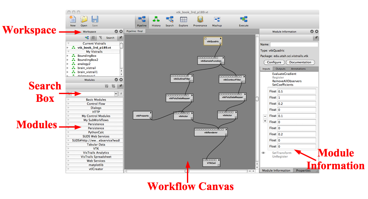
The main VisTrails Pipeline user interface. The major components are labeled.
Modules and connections may be selected in multiple ways and are denoted by a yellow highlight. Besides directly left clicking on the object, a box selection is available by left clicking and dragging over the modules and connections in the canvas. Multiple selection can be performed with the box selection as well as by right clicking on multiple objects with the ‘Shift’ key pressed.
There are several ways to manipulate selected modules in the workflow canvas. Moving them is performed by dragging a selected module using the left mouse button. Deleting selected modules is performed by pressing the ‘Delete’ key. The modules and connections can also be copied and pasted using the Edit menu, or with ‘Ctrl-C’ and ‘Ctrl-V’, respectively.
Try it now!
Let’s replace the vtkQuadric module in our example with a vtkCylinder module instead. To do this, first type “vtkCylinder” into the search box of the Module container. As the letters are typed, the list filters the available modules to match the query. Select this module and drag the text onto an empty space in the canvas (see Figure The vtkCylinder module is added to the canvas). Then, select the vtkQuadric module in the canvas and press the ‘Delete’ key. This removes the module along with any connections it has (see Figure The vtkQuadric module is deleted).
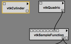
The vtkCylinder module is added to the canvas.
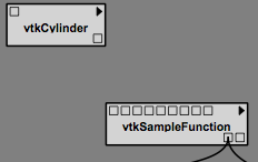
The vtkQuadric module is deleted.
Connecting Modules
Modules are connected in VisTrails through the input and output ports at the top and bottom of the module, respectively. By hovering the mouse over the box that defines a port, the name and data type are shown in a small tooltip. To connect two ports from different modules, start by left clicking inside one port, then dragging the mouse to the other. The connection line will automatically snap to the ports in a module that have a matching datatype. Since multiple ports may match, hovering the mouse over the port to confirm the desired match may be necessary. Once a suitable match is found, releasing the left mouse button will create the connection. Note, a connection will only be made if the input and output port’s data types match. To disconnect a connection between modules, the line between the modules can be selected and deleted with the ‘Delete’ key.
Try it now!
To connect the vtkCylinder module to the vtkSampleFunction module, place the cursor over the only output port on the vtkCylinder module, located on the bottom right. A tooltip should appear that reads “Output port self (vtkCylinder).” Left click on the port and drag the mouse over the vtkSampleFunction module. The connection should snap to the fourth input port from the left. Hovering the mouse over this port shows a tooltip that reads “Input port SetImplicitFunction (vtkImplicitFunction).” Release the mouse button to complete the connection between these two modules (see Figure The connection replaced). To check for a valid dataflow, execute the workflow by pressing the Execute button on the toolbar, and see if the results appear in the spreadsheet.
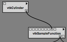
The connection replaced.
Changing Module Parameters
The parameters for a module can be accessed in the Module Information tab located on the right side of the Builder window. When a module on the canvas is selected, the corresponding module information is displayed. The Inputs, Outputs, and Annotations tabs can be selected to set parameters within the respective categories. To set a parameter, simply click on its name to reveal its input box and enter the desired value. Notice that a - and + button appears to the left of the input box. The - button removes the corresponding input box and the + button adds one. This allows you to experiment with different values, but only the values in the last box are used in the final result.
Try it now!
To perform a parameter change, select the vtkCylinder module in the canvas. Select SetRadius, enter 0.25 into the text box and press the ‘Enter’ key. By executing the workflow, the modified visualization appears in the spreadsheet. Figures The module methods... and The results... show the interface and results of the parameter explorations.
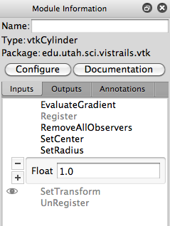
The module methods interface is shown with a change of the SetRadius parameter to 1.0.

The results of the changes are displayed on execution.
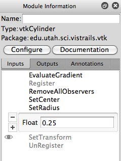
The module methods interface is shown with a change of the SetRadius parameter to 0.25.
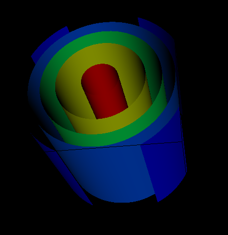
The results of the changes are displayed on execution.
Using Global Variables
VisTrails supports the use of global variables, which allows the user to create a variable which can be used anywhere within the vistrail. So, if you create a variable of type String, you can assign that variable to any port of type String. This is done by opening the Vistrail Variables view, creating a variable, and then dragging it to the desired port.
Try it now!
Open vtk_http.vt and go to the Pipeline view of the Fran Cut Smoothed version. Select Views Vistrail Variables. Select the String module from Basic Modules, drag it over to the Vistrail Variables tab, and drop it (see Figure Create a Variable...). Name it ‘Filename1’ and assign it the following value: ‘http://www.sci.utah.edu/~cscheid/stuff/vtkdata-5.0.2.zip‘. Click on String, which is just below Filename1 in the Vistrail Variables tab. Drag it over and drop it in the port of the HTTPFile (as shown in Figure Assign a Variable...). The variable should be assigned and the port should be filled in with yellow.
To delete a global variable, simply click on the ‘X’ button that appears to the right of its name. This will remove the variable, but if any ports are assigned to it, they need to be disconnected. You can do this by right-clicking on the port and selecting Disconnect Vistrail Variables (see Figure Disconnect a Variable...).
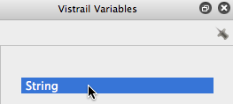
Create a Variable - Drag the String module and drop it in the Vistrail Variables tab to create a global variable.
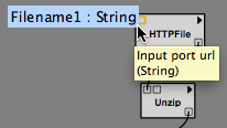
Assign a Variable - Drag the type from just below the Global Variables name on the Vistrail Variables tab. Drop it on a port to set the variable.
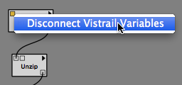
Disconnect a Variable - To disconnect a global variable, right click on the assigned port and select Disconnect Vistrail Variables.
Configuring Module Labels
To give the module a custom name, enter it in the Module Information tab’s Name box. The modules name will be displayed with the original module name(type) displayed in parenthesis below it.
Configuring Module Ports
For convenience, all the inputs and outputs of a module are not always shown in the canvas as ports. The ports that are shown by default are defined with the method signatures of a package. A full list of ports is available in the Module Configuraton window, which is accessed by clicking on the Configure button in the module information tab or pressing ‘Ctrl-E’ when a module is selected. Alternatively, module ports can be enabled/disabled by clicking in the left margin next to the port name in the Inputs or Outputs tabs of the Module Information tab (see Figure Enabling the GetRadius port from the Module Information tab). When enabled, an eye icon will appear to the left of the port name. New ports will appear on the module with a circle icon instead of a square to signify that they are not visible by default, but can be connected in the same way as the others.
Try it now!
As an example of configuring a module port, select the vtkCylinder module in the canvas, select Outputs from the Module Information tab, and click in the left margin next to GetRadius (see Figure Enabling the GetRadius port from the Module Information tab). A new circle port should appear on the module. Next, add a new StandardOutput module from the basic modules and connect the output port for GetRadius to the input port of StandardOutput. Upon execution, the value 0.25 is now output to the console. Figure The vtkCylinder module... shows the new workflow.

Enabling the GetRadius port from the Module Information tab.
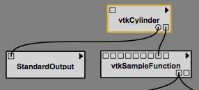
The vtkCylinder module is configured to show an additional GetRadius port, which is then connected to a StandardOutput module.
Basic Modules
In addition to the modules provided by external libraries, VisTrails provides a few basic modules for convenience and to facilitate the coupling of multiple packages in one workflow. These modules mostly consist of basic data types in Python and some manipulators for them. In addition, file manipulation modules are provided to read files from disk and write files to disk.
PythonSource
Because not every Python operation can be represented as a module, the PythonSource module is provided to allow you to write Python statements to be executed as part of a workflow. By pressing ‘Ctrl-E’ when a PythonSource module is selected in the canvas, a configuration window is opened. This window allows you to specify custom input and output ports as well as directly enter Python source to be executed in the workflow.
Note
Sometimes is it useful to view the source code that is contained in the PythonSource module when working with other modules. Since the PythonSource configuration window will disappear when you select a new module, a Show read-only window button can be used to open a read-only window of the PythonSource's configuration, which will remain open until it is closed.
Try it now!
To demonstrate a PythonSource module, we will output the center of the cylinder using Python instead of the StandardOutput module. First, add a PythonSource module to the canvas and remove the StandardOutput module. Select the PythonSource module and press ‘Ctrl-E’ to edit the configuration. In the newly opened configuration window, create a new input port named “radius” of type Float. Next, in the source window enter:
print radius
then select OK to close the window. Finally, connect the GetRadius output of the vtkCylinder module to the new input port of PythonSource. Upon execution, the radius of the cylinder is printed to the console as before. Figure A PythonSource module can be used to directly insert scripts into the workflow shows the new workflow together with the PythonSource configuration window.
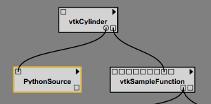
A PythonSource module can be used to directly insert scripts into the workflow.
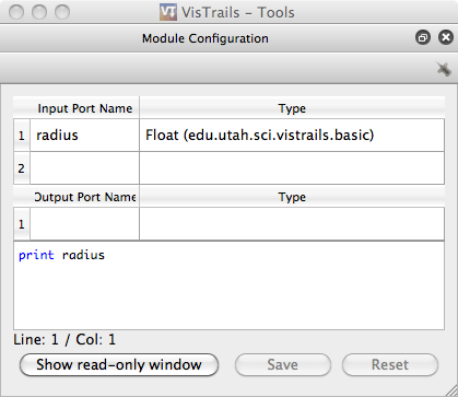
The configuration window for PythonSource allows multiple input and output ports to be specified along with the Python code that is to be executed.
Accessing vtkObjects in PythonSource When using a PythonSource module, users will often rely on their knowledge of VTK to interact with VTK modules. It is important to realize that a VTK module is really a wrapping of a vtkObject. The real vtkObject is called vtkInstance, meaning the vtkObject of a module called ‘dataset’ is called ‘dataset.vtkInstance’ (see figure Accessing vtkObjects...).
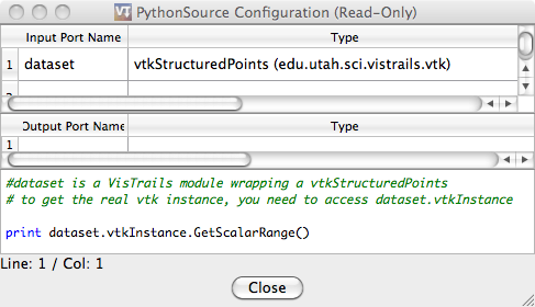
Accessing vtkObjects - The vtkObject of a VTK module, ‘dataset’, is accessed with ‘dataset.vtkInstance’.