Creating and Modifying Workflows
Working with Modules
In VisTrails, modules are represented by a rectangle in the Pipeline view of the Builder. The name of the module is shown in bold letters in the middle of the rectangle. The input and output ports for the module are denoted by small squares on the top and bottom of the module, respectively. Modules are connected together to define the dataflow using curved black lines that go from output to input ports between modules. Each module may have also have adjustable parameters that can be viewed when a module is selected. Modules can be connected, disconnected, added, and deleted from a workflow.
As a running example in this chapter, we will make some changes to the “vtk_book_3rd_p189.vt” vistrail, included in the “examples” folder of the VisTrails installation.
Try it now!
Open the “vtk_book_3rd_p189.vt” vistrail, either by selecting File  Open from the menu, or by clicking the Open button on the toolbar. After opening this vistrail, click on the Pipeline toolbar button to enter workflow editing mode.
Adding and Deleting Modules
A list of available modules is displayed hierarchically in the Modules container on the left side of the VisTrails Builder (Figure The main VisTrails Pipeline user interface. The major components are labeled.). A core set of basic modules is always distributed with the VisTrails system. Other packages, such as VTK, are also distributed, but are not necessary for VisTrails and thus can be disabled on startup (see Chapter Writing VisTrails Packages). Note, however, that the VTK module is required for most of the examples in this book. Depending on the number of packages imported on startup, the number of modules to select from can be difficult to navigate. Thus, a simple search box is provided at the top of the container to narrow the displayed results. To add a module to the workflow, simply drag the text from the Module container to the workflow canvas.
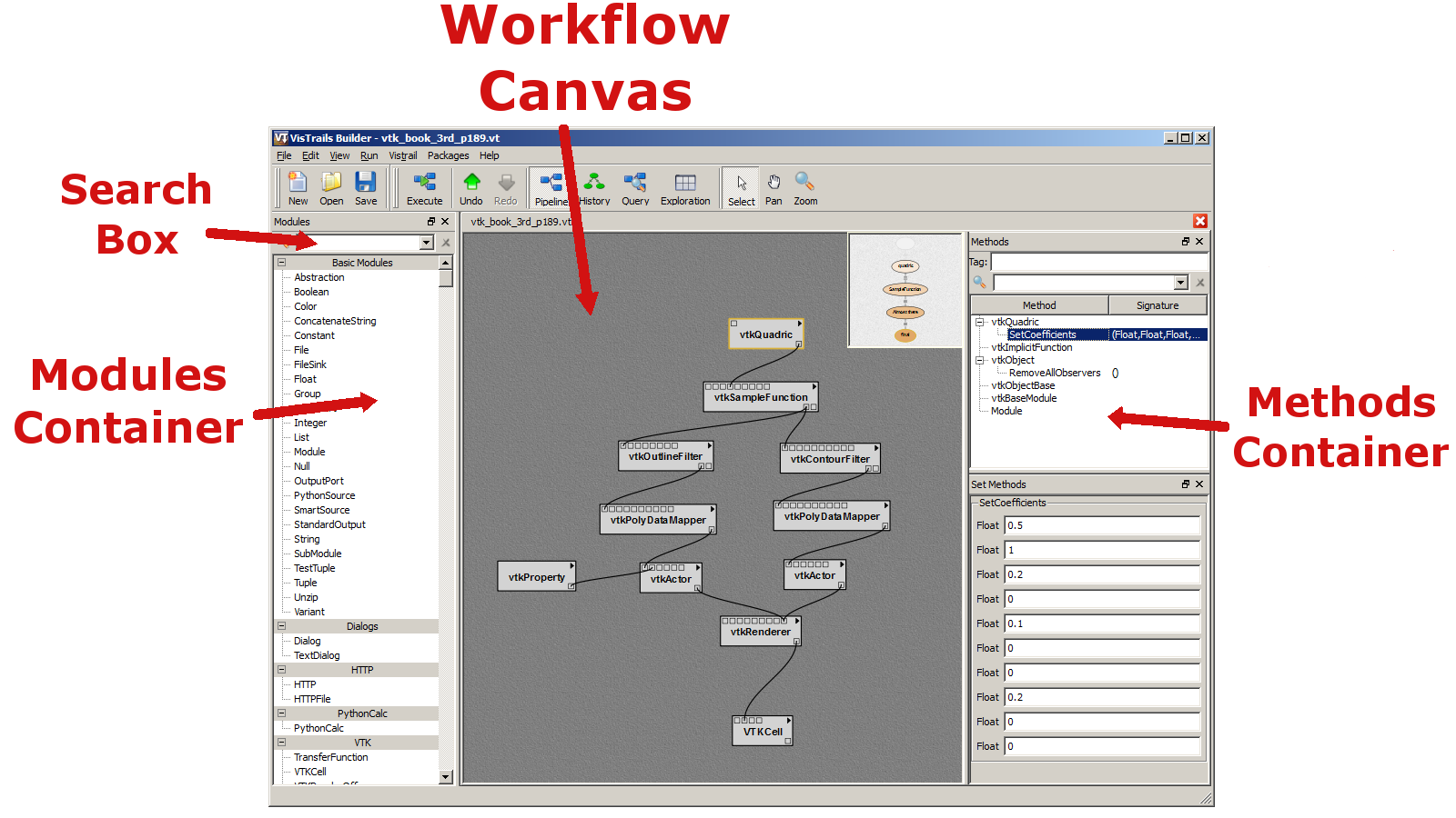
The main VisTrails Pipeline user interface. The major components are labeled.
Modules and connections may be selected in multiple ways and are denoted by a yellow highlight. Besides directly left clicking on the object, a box selection is available by left clicking and dragging over the modules and connections in the canvas. Multiple selection can be performed with the box selection as well as by right clicking on multiple objects with the ‘Shift’ key pressed.
There are several ways to manipulate selected modules in the workflow canvas. Moving them is performed by dragging a selected module using the left mouse button. Deleting selected modules is performed by pressing the ‘Delete’ key. The modules and connections can also be copied and pasted using the Edit menu, or with ‘Ctrl-C’ and ‘Ctrl-V’, respectively.
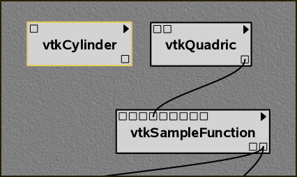
The vtkCylinder module is added to the canvas.
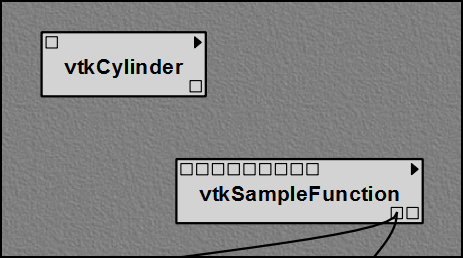
The vtkQuadric module is deleted.
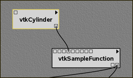
The connection replaced.
Try it now!
Let’s replace the vtkQuadric module in our example with a vtkCylinder module instead. To do this, first type “vtkCylinder” into the search box of the Module container. As the letters are typed, the list filters the available modules to match the query. Select this module and drag the text onto an empty space in the canvas. (See Figure The vtkCylinder module is added to the canvas.. Then, select the vtkQuadric module in the canvas and press the ‘Delete’ key. This removes the module along with any connections it has (see Figure The vtkQuadric module is deleted.).
Connecting Modules
Modules are connected in VisTrails through the input and output ports at the top and bottom of the module, respectively. By hovering the mouse over the box that defines a port, the name and data type are shown in a small tooltip. To connect two ports from different modules, start by left clicking inside one port, then dragging the mouse to the other. The connection line will automatically snap to the ports in a module that have a matching datatype. Since multiple ports may match, hovering the mouse over the port to confirm the desired match may be necessary. Once a suitable match is found, releasing the left mouse button will create the connection. Note, a connection will only be made if the input and output port’s data types match. To disconnect a connection between modules, the line between the modules can be selected and deleted with the ‘Delete’ key.
Try it now!
To connect the vtkCylinder module to the vtkSampleFunction module, place the cursor over the only output port on the vtkCylinder module, located on the bottom right. A tooltip should appear that reads “Output port self (vtkCylinder).” Left click on the port and drag the mouse over the vtkSampleFunction module. The connection should snap to the fourth input port from the left. Hovering the mouse over this port shows a tooltip that reads “Input port SetImplicitFunction (vtkImplicitFunction).” Release the mouse button to complete the connection between these two modules (see Figure The connection replaced.. To check for a valid dataflow, execute the workflow by pressing the Execute button on the toolbar, and see if the results appear in the spreadsheet.
Changing Module Parameters
The parameters for a module can be accessed in the Methods container located on the right side of the Builder window. When a module is selected from the canvas, the corresponding methods are displayed. As with the Modules container, a search box is provided to quickly find a desired method. By default, the Builder only manages methods with “set parameters.” To check the set parameters, a Set Methods container is available below the Methods container. Changing a parameter can be performed directly in the Set Methods container. To set a parameter for the first time, click on the corresponding method and drag it into the Set Methods container, then enter the parameters directly into the text boxes. To remove a method, simply select the method in the Set Methods container and press the ‘Delete’ key.
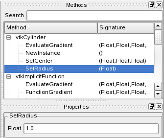
The module methods interface is shown with a change of the SetRadius parameter to 1.0.
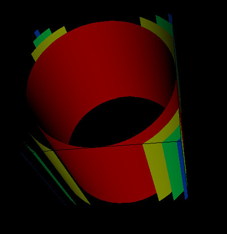
The results of the changes are displayed on execution.
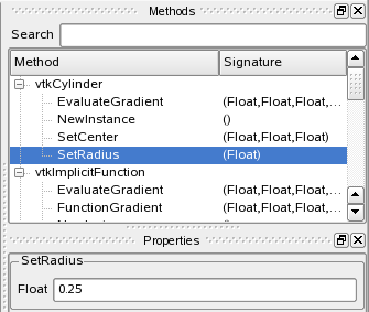
The module methods interface is shown with a change of the SetRadius parameter to 0.25.
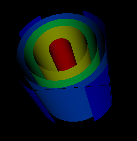
The results of the changes are displayed on execution.
Try it now!
To perform a parameter change, select the vtkCylinder module in the canvas. The methods are shown hierarchically in the Methods container. Find the SetRadius method and select it, then drag the highlighted text from the Methods container into the Set Methods container below. The result is a SetRadius box with a Float text input. Enter 0.25 into the text box and press the ‘Enter’ key. By executing the workflow, the modified visualization appears in the spreadsheet. Figure The module methods interface is shown with a change of the SetRadius parameter to 1.0. shows the interface and results of the parameter explorations.
Changing Module Labels
A new label can be assigned to a module by selecting the triangle in its top right corner to open a popup menu and selecting the Set Module Label... menu item. You will then be prompted to enter the new label. The new label will be displayed in the prominent position and the original module name will be displayed below it in parenthesis.
Configuring Module Ports
For convenience, all the inputs and outputs of a module are not always shown in the canvas as ports. The ports that are shown by default are defined using an option when defining the method signatures of a package. To access the full list of ports, the module configuration window is used. This is opened by selecting the triangle at the top right of a module to open a popup menu and selecting the Edit Configuration menu item, or alternatively by pressing ‘Ctrl-E’ when a module is selected. The window shows a list of input and output ports and allows you to toggle any additional ports to enable. When the configuration is complete, the new ports will appear on a module with a circle icon instead of the normal square. These new ports can then be used for connections in the same way as the others.
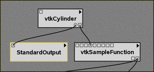
The vtkCylinder module is configured to show an additional GetRadius port, which is then connected to a StandardOutput module.
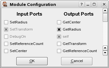
The module configuration window allows the hidden ports to be displayed.
Try it now!
As an example of configuring a module port, select the vtkCylinder module in the canvas and press ‘Ctrl-E’. In the newly opened configuration window, check the box for the GetRadius port, then click OK to close the window. A new circle port should appear on the module. Next, add a new StandardOutput module from the basic modules and connect the output port for GetRadius to the input port of StandardOutput. Upon execution, the value 0.25 is now output to the console. Figure The vtkCylinder module is configured to show an additional GetRadius port, which is then connected to a StandardOutput module. shows the new workflow together with the module configuration window.
Grouping Modules
As the number of modules in a pipeline increases, the pipeline can grow quite large and cumbersome. This also makes the pipeline more difficult to understand and maintain. With any large system, it can be helpful to cluster related pieces together and represent them as a single unit. This idea, called encapsulation, is commonly used in computer programming as a way of controlling complexity. VisTrails likewise supports the grouping of multiple modules together so that they can be treated as a single module. This “group module” can be thought of as a monolithic entity that performs all the same functions as its individual parts, but shields its inner details from everyone else. As such, a group module inherits all the input and output ports of the modules inside it, but only displays those ports that have connections to another module outside of the group. To borrow another term from programming languages, these visible ports might be considered the public interface of the group module.
Multiple modules are grouped together by first selecting them, and then choosing the Group option from the Edit menu. Alternatively, you can use the keyboard shortcut ‘Ctrl-G’.
An example may clarify how this works.
Try it now!
Select the vtkOutlineFilter, vtkPolyDataMapper, vtkProperty, and vtkActor modules on the left side of the pipeline, as shown in Figure Box selection of four modules.. Type ‘Ctrl-G’ to group these modules. Notice how the pipeline changes, as shown in Figure The modules represented as a single group module.. Since the label “Group” isn’t very descriptive, you can change this by clicking on the triangle in the top right of the module, and selecting the Set Module Label menu option. Type a more descriptive name, such as “BoundingBox,” into the text field and click OK. The new label is reflected in the pipeline (Figure Renaming the group.).
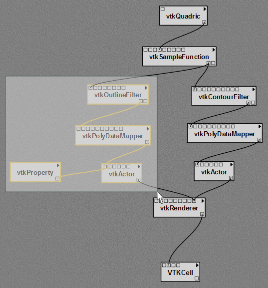
Box selection of four modules.
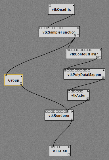
The modules represented as a single group module.
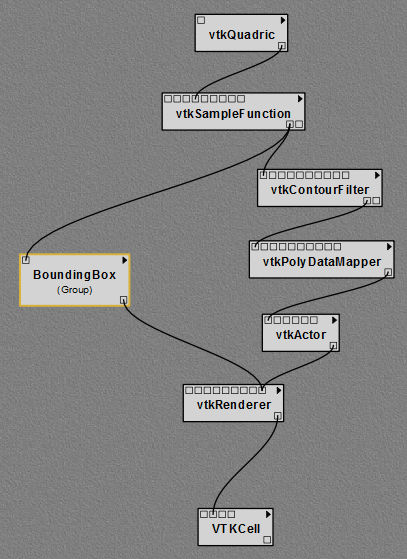
Renaming the group.
Just as any number of modules may be clustered into a group, any number of groups may be combined with other groups or modules to form still larger groups. This is done in the same way as described above.
In addition, any group may be also un-grouped; that is, restored to its individual modules. This is done by selecting the group module in the pipeline, and then choosing the Edit Ungroup menu option. Alternatively, you can use the keyboard shortcut ‘Ctrl-Shift-G’.
Basic Modules
In addition to the modules provided by external libraries, VisTrails provides a few basic modules for convenience and to facilitate the coupling of multiple packages in one workflow. These modules mostly consist of basic data types in Python and some manipulators for them. In addition, file manipulation modules are provided to read files from disk and write files to disk.
Because not every Python operation can be represented as a module, the PythonSource module is provided to allow you to write Python statements to be executed as part of a workflow. By pressing ‘Ctrl-E’ when a PythonSource module is selected in the canvas, a configuration window is opened. This window allows you to specify custom input and output ports as well as directly enter Python source to be executed in the workflow.
Try it now!
To demonstrate a PythonSource module, we will output the center of the cylinder using Python instead of the StandardOutput module. First, add a PythonSource module to the canvas and remove the StandardOutput module. Select the PythonSource module and press ‘Ctrl-E’ to edit the configuration. In the newly opened configuration window, create a new input port named “radius” of type Float. Next, in the source window enter:
print radius
then select OK to close the window. Finally, connect the GetRadius output of the vtkCylinder module to the new input port of PythonSource. Upon execution, the radius of the cylinder is printed to the console as before. Figure A PythonSource module can be used to directly insert scripts into the workflow. shows the new workflow together with the PythonSource configuration window.
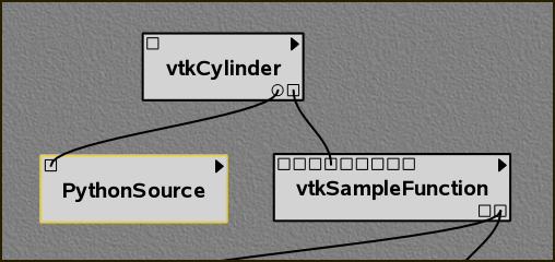
A PythonSource module can be used to directly insert scripts into the workflow.
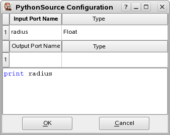
The configuration window for PythonSource allows multiple input and output ports to be specified along with the Python code that is to be executed.